How To Correctly Mark The Lower Primary Hull Concentric Rings On The AMT 1:650 TOS Enterprise Model Kit
Hi, Everyone!
The AMT / ERTL / Round 2 1:650 TOS U.S.S. Enterprise model is widely regarded as a classic kit. However, that has never meant that it is a perfect kit. Far from it, actually. When the model was tooled in 1966, it had plenty of accuracy issues. Then when many of the parts were re-tooled in the early 1970s, even more problems were introduced.
One of the trouble spots that has never been addressed are the three concentric rings on the lower primary hull part. From the start, AMT had it wrong. The tooling created three raised rings which were not correctly sized or spaced. Modelers who wish to try accurizing that area usually start by sanding away those rings. But what are the measurements for a new set of rings?
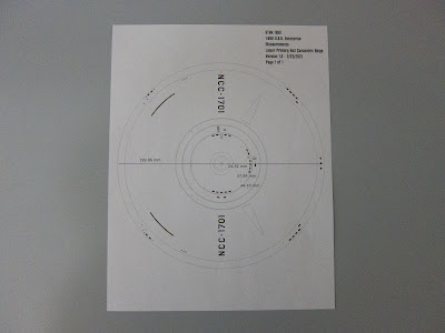
First, find yourself a detailed image of the lower primary hull that you trust is accurate. Personally, I went with a vector-based image that was used for the Polar Lights 1:1000 TOS Enterprise model kit. This is based off Star Trek historian and filming miniature information archivist extraordinaire Gary Kerr's researched drawings. (In fact, when Polar Lights was designing the 1:1000 TOS Enterprise model, Gary was a consultant for the project and was ultimately the reason why that little kit is so accurate to the 11-foot filming miniature.) The AMT kit's lower primary hull part is about 200 mm in diameter. So in software, I scaled up the drawing to match that size.
Next, again using the drawing software, I measured the distances from the center of the lower saucer to the three rings. I came out with measurements of 29.82 mm, 37.84 mm, and 44.43mm. One thing, though, the two-dimensional drawing does not account for the curves / slopes of the physical object it represents. It is merely a direct top-down view. So how do you reflect these measurements correctly onto the surface of the model kit part?
My solution was to use a contour gauge. This is a hardware tool that uses a series of pins to measure / duplicate edge and corner contours. Using it along one half of the model part, the tool reproduced the shape of the lower saucer. I noted which pin represented the center. I then used a digital caliper to measure out the three ring distances, also noting / marking which pin they fell upon. Afterwards, I put the contour gauge back into position against the model part and marked the top-down measurements onto the plastic surface.
And that's really it! To finish off, just scribe the rings using a compass cutter and the markings on the plastic.
Check out the pictures below where I used my described method with a practice kit. In the pictures, you can see the set of rings I scribed in years ago when at the time I just wanted to "eyeball it." That, of course, didn't work out. :D
Here is the list of hardware parts I used:
- Pittsburgh 6-inch Contour Gauge - https://www.harborfreight.com/6-inch-contour-gauge-907.html
- Pittsburgh 6-inch Digital Caliper With SAE And Metric Fractional Readings - https://www.harborfreight.com/6-in-digital-caliper-with-sae-and-metric-fractional-readings-63731.html
- Daiso Compass Cutter - https://www.daisojapan.com/p-20752-compass-cutter-12pks.aspx - if you have a local Daiso store, you can usually pick one up for less than $2.00 U.S.D.
I hope this helps with anyone building the AMT / ERTL / Round 2 1:650 TOS U.S.S. Enterprise kit. If you have any questions, let me know.
Happy modeling!
:)


Comments
Post a Comment